Arduino programming empowers creators, engineers, and hobbyists alike to build interactive electronic systems. At the core of this programming lies the concept of using input and output variables to control sensors, actuators, lights, motors, and more. Understanding how values are passed into and retrieved from an Arduino board is essential for building responsive and functional embedded systems.
TL;DR
Input and output variables in Arduino programming represent the data a system receives and sends through its pins. Input variables pull in information from sensors or buttons, while output variables send signals to devices like LEDs and motors. These concepts allow for effective interaction between hardware and software in embedded systems. Proper handling and structuring of I/O variables lead to accurate data flow, efficient logic processing, and predictable system behavior.
What Are Input & Output Variables?
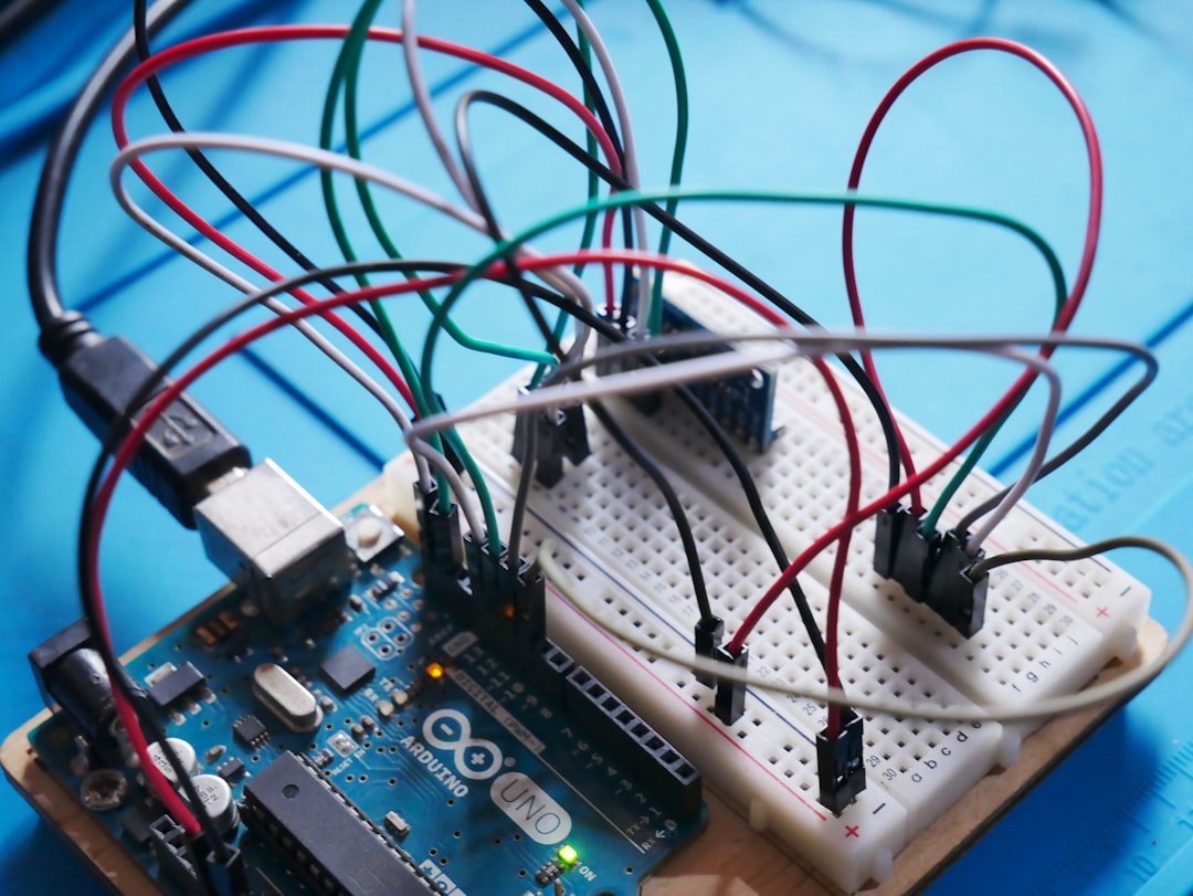
At its core, any Arduino project aims to receive data, process it, and produce a result. Inputs are the way a system collects real-world data, and outputs are how it responds to that data. These elements are represented and controlled using variables in your Arduino sketch (the program written to run on the board).
For example, when you press a button, the Arduino reads the state of that button as an input. Then, depending on the logic you’ve defined, it may turn on an LED, which is controlled via an output.
Understanding the Role of Input Variables
An input variable in Arduino is a variable that stores data received from an input pin. Usually, these inputs are connected to components such as:
- Push buttons
- Temperature sensors
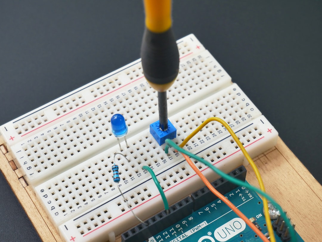
- Potentiometers
- Ultrasonic distance sensors
- Light-dependent resistors (LDRs)
In your Arduino sketch, inputs are typically declared and read using functions like pinMode() and digitalRead() or analogRead():
const int buttonPin = 2;
int buttonState = 0;

void setup() {
  pinMode(buttonPin, INPUT); // Declare pin as input
}

void loop() {
  buttonState = digitalRead(buttonPin); // Read input value
}
In this code, buttonPin is assigned to pin 2, which might be connected to a button. buttonState is the variable used to store the value read from that input—either HIGH (1) or LOW (0).
Defining and Using Output Variables
On the flip side, an output variable stores values that represent what the Arduino sends to its output components. These can include:
- LEDs
- Relays
- Piezo buzzers
- Servo motors
- LCD displays
Like with inputs, you establish outputs using pinMode() and set their value using digitalWrite() or analogWrite() (for PWM-enabled pins):
const int ledPin = 13;

void setup() {
  pinMode(ledPin, OUTPUT); // Declare pin as output
}

void loop() {
  digitalWrite(ledPin, HIGH); // Turn LED on
  delay(1000);
  digitalWrite(ledPin, LOW);  // Turn LED off
  delay(1000);
}
In this example, ledPin represents pin 13, usually wired to an onboard or external LED. The loop function toggles the LED state by writing HIGH or LOW values.
Variable Types and Their Impact
It’s important to choose the correct variable types when dealing with input and output values to reflect the kind of data being processed. Below are common Arduino variable types used:
int– For storing integer values (e.g., analog sensor readings, pin numbers).boolean– For storing true/false conditions (ideal for simple digital input states).float– For precise sensor data requiring decimal calculations (e.g., temperature, distance).byte– For efficient use when values range 0–255 (e.g., for PWM brightness control).
Choosing the wrong variable type can cause inaccurate readings or unintended behaviors. For example, using an int where a float is required may lead to loss of precision.
Real-World Example: Combining Inputs and Outputs
Let’s look at a practical example to illustrate how inputs and outputs are used together. Suppose you want to build a system where pressing a button toggles an LED on and off.
const int buttonPin = 2;
const int ledPin = 13;

int buttonState = 0;
int lastButtonState = 0;
int ledState = LOW;

void setup() {
  pinMode(buttonPin, INPUT);
  pinMode(ledPin, OUTPUT);
}

void loop() {
  buttonState = digitalRead(buttonPin);

  if (buttonState == HIGH && lastButtonState == LOW) {
    if (ledState == LOW) {
      ledState = HIGH;
    } else {
      ledState = LOW;
    }
    digitalWrite(ledPin, ledState);
  }

  lastButtonState = buttonState;
}
This sketch uses several variables to track the state of the button and the LED. Notably, it avoids toggling the LED continuously by checking if the button was just pressed, a concept known as edge detection.
Best Practices When Working with Arduino I/O Variables
While handling I/O is straightforward, robust and scalable designs benefit from following a set of best practices:
- Use Meaningful Names: Name your input/output variables based on their function (e.g.,
photoSensorPin,motorSpeed). - Minimize Global Variables: Use local scope where possible to avoid accidental modification of system-critical values.
- Comment Your Code: Explain what inputs and outputs do for easier debugging and collaboration.
- Debounce Mechanical Inputs: Use software techniques to filter unstable input signals from buttons or switches.
- Use Constants for Pin Assignments: Avoid magic numbers in code by declaring pin references using
const.
Digital vs Analog I/O
The Arduino platform supports two primary types of I/O:
Digital I/O
Digital inputs and outputs deal with binary signals—either ON or OFF, HIGH or LOW. Examples include buttons and LEDs.
Analog I/O
Analog inputs can sense a range of values. These provide much finer control, such as reading light levels or pressure. Arduino boards interpret analog sensor input in a 10-bit range (0 to 1023).
Some Arduino boards also allow for analog output using PWM (Pulse Width Modulation), which mimics the behavior of analog voltage for devices like motors or dimmable LEDs.
Debugging Input and Output Issues
Often, a program doesn’t behave as expected because of undetected errors in input and output behavior. Use these debugging tips:
- Check Pin Mappings: Ensure sensors and actuators physically connect to the correct GPIO pin numbers defined in code.
- Use
Serial.print(): Output intermediate values to the serial monitor to track variable states in real-time. - Test Simpler Configurations: Isolate the input or output separately to check its behavior before integrating it into a full system.
Conclusion
Understanding and leveraging input and output variables in Arduino programming is foundational for anyone hoping to make the most of embedded electronics. These variables serve as the channels through which real-world interactions happen—from sensing the environment to controlling outputs based on conditions. Mastery of I/O brings with it the confidence to tackle more advanced projects, manipulate data smartly, and build reliable hardware systems.
Ultimately, successful Arduino programming comes down to careful tracking of input and output flow, precise data management, and a solid grasp of how your devices communicate with the world around them through code.
